❌

Vista elenco

Rigorous Analysis Confirms NASA’s Artemis II Heat Shield Performance 

15 Ottobre 2026 ore 16:57
A post‑mission comparison of the Orion spacecraft heat shields from Artemis I (left) and Artemis II (right) are shown after removal from their crew modules. Both heat shields are seen rotated for inspection inside the Operations and Checkout Building at NASA’s Kennedy Space Center in Florida.
NASA

NASA’s Artemis II mission sent four astronauts around the Moon and brought them safely back to Earth, laying a foundation for crewed flights to the Moon’s surface.

Additional engineering data analysis of the Orion spacecraft’s heat shield confirmed initial data showing the heat shield performed as expected.  

In particular, NASA measured whether the thermal protection system effectively safeguarded the crew and Orion systems as the spacecraft reentered Earth’s atmosphere. This test flight was the first time astronauts flew aboard Orion. 

Orion reached a maximum velocity of 39 times the speed of sound and experienced external temperatures exceeding 4,000 degrees Fahrenheit at its peak, all while the four astronauts inside Orion stayed relatively cool with a cabin temperature in the mid-70 degree Fahrenheit range during their return to Earth from the Moon.  

After NASA’s thorough analysis of Artemis I heat shield findings, informed by extensive arc jet material testing at NASA’s Ames Research Center in California’s Silicon Valley, the agency modified Orion’s reentry trajectory for Artemis II by shortening the maximum downrange distance the spacecraft could fly between when it entered Earth’s atmosphere and splashed down in the Pacific Ocean. Analysis prior to the mission showed that limiting downrange distance would limit how long the spacecraft’s heat shield spent in the temperature range at which the Artemis I heat shield phenomenon occurred.  
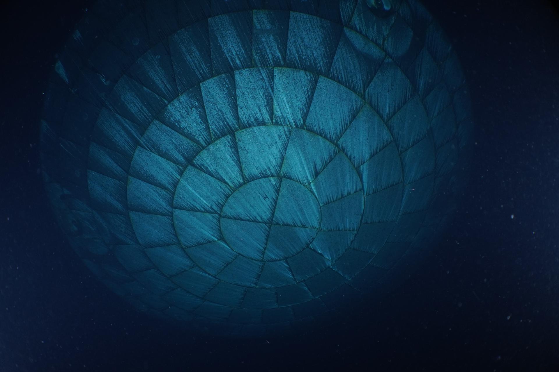
Shortly after Artemis II splashdown on April 10, 2026, U.S. Navy divers captured underwater imagery of the Orion spacecraft’s heat shield.
US Navy

The spacecraft reentered with precision, entering within only 192 feet of its targeted entry interface, and successfully splashed down only 0.59 miles from the predicted landing site off the coast of San Diego. Initial inspections of the thermal protection system, including diver imagery of the spacecraft’s heat shield taken just after splashdown and further inspections on the recovery ship, found it performed as expected, with a significant reduction in the amount of cracks and char loss as compared to Artemis I.  

Upon the spacecraft’s return to NASA’s Kennedy Space Center in Florida after the Moon mission, thermal protection system experts began additional examination of the heat shield, made of 186 unique blocks of an ablative material called Avcoat. The heat shield was then transported to NASA’s Marshall Space Flight Center in Huntsville, Alabama, where work on sample extraction and internal x-ray scans began in August to provide further engineering insight into the system and behavior of the material.
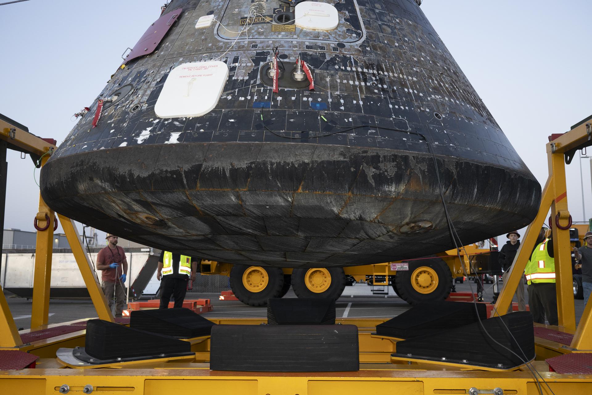
The Artemis II Orion crew module after being offloaded from the well deck of USS John P. Murtha at Naval Base San Diego and lifted from the Orion Recovery Cradle Assembly on April 18, 2026. The gray area, as seen on the edge where the spacecraft’s heat shield and the backshell meet, is from recovery operations.
NASA/Kevin Davis

A thorough post-flight assessment review found that Orion’s aerodynamic and aerothermal performance, including the heat shield and backshell thermal protection system, was in line with engineering predictions based on pre-flight analyses and ground testing. The shorter allowable down range during entry reduced the cracking and char loss experienced on the Artemis II heat shield relative to the Artemis I heat shield by a factor of ten, proving the effectiveness of the trajectory modification. Engineers found only nine spots of char loss of varying sizes on the Artemis II heat shield dish, compared to 103 during Artemis I. 

The analysis also showed that Orion’s robust heat shield design showed consistency from Artemis I to Artemis II, evident by the performance of system features such as the seams between the heat shield Avcoat blocks and the Avcoat surrounding the heat shield compression pad separation bolts. 

Post-flight inspection of Orion’s backshell, the protective cover on the sloped sides of the crew module made up of 1,300 ceramic tiles, showed expected performance across the crew module surface. Visual inspections indicated backshell features designed to seal and protect penetrations such as windows, vents, thrusters, and the side hatch also met expectations, with no signs of overheating observed. 

The team also performed post-flight laser scans of the heat shield surface and is comparing this data to pre-flight measurements to determine material recession, which will then be compared to analysis predictions. Engineers are continuing with heat shield sample extraction at NASA Marshall and subsequent material test and assessment and thermal analysis, to support long-term heat shield development, manufacturing efforts, and data capture. 
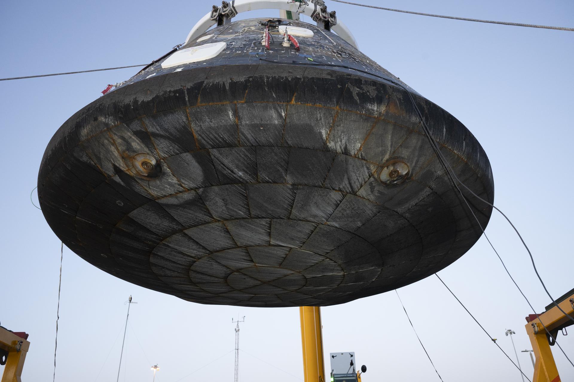
The Artemis II Orion crew module is lifted from its recovery fixture for inspection and engineering imagery after being offloaded from the USS John P. Murtha at Naval Base San Diego on April 18, 2026. The recessed areas, or smaller concentric circles, seen on the heat shield are associated with the separation bolts that connect the crew module with the service module. The larger circular patterns are formed due to compression pad material used within this location of the spacecraft, creating flow disturbances caused by extreme aerodynamic and thermal airflow during reentry. This causes increased heating locally and therefore Avcoat ablator thickness is increased in these areas by design.
NASA/Kevin Davis

Orion’s performance and the team’s analysis on Artemis II reflect system robustness, capability to support crew, and critical insights gathered that will enhance the Artemis III mission and beyond. Following the extensive Artemis I heat shield investigation, upgrades were made to the heat shield design for Artemis III to achieve uniformity and consistent permeability of the Avcoat blocks. Technicians attached the heat shield for the Artemis III Orion crew module at NASA Kennedy in early July, and the Orion crew and service modules were joined at the end of July. The spacecraft has since been successfully powered up for the first time, enabling engineers to check all connection lines between the two modules are working as planned.
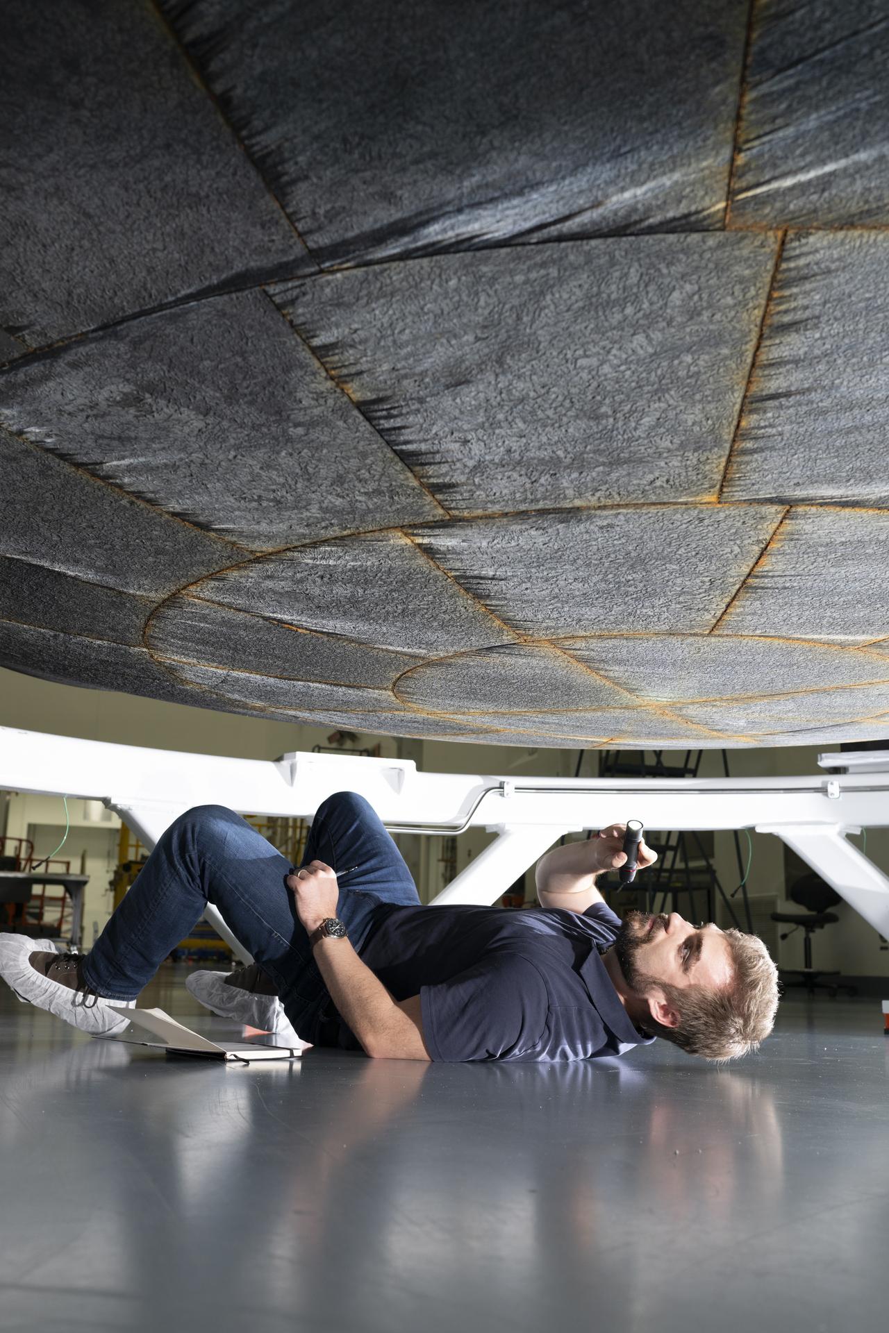
A person lies on the floor of a workshop, holding a flashlight to inspect the underside of a large, circular heat-shield-like structure suspended above them. The individual is positioned on their side beneath the hardware, with tools and equipment visible in the background.
An engineer from NASA’s Ames Research Center inspects the Artemis II Orion heat shield at NASA Kennedy’s Multi-Purpose Payload Facility on April 30, 2026, prior to its removal from the crew module. The orange tint seen between Avcoat tiles is an expected effect of the silicone used to fill the gaps between the blocks. The silicone gap filler contains iron oxide, which gives it a red appearance after enduring reentry. 
NASA/Kevin Davis

NASA continues to advance toward Artemis III as teams ready the Orion spacecraft for next year’s mission in low Earth orbit. NASA will launch the SLS (Space Launch System) rocket and Orion spacecraft with NASA astronauts Randy Bresnik, Frank Rubio, Andre Douglas, and ESA (European Space Agency) Luca Parmitano, to rendezvous with human lander test articles from Blue Origin and SpaceX to demonstrate critical systems and operations needed for future lunar landings, beginning with Artemis IV in 2028.
NASA’s Chandra Breaks Down ‘Treble Clef’s’ Galaxy Cluster Collision

14 Ottobre 2026 ore 18:46
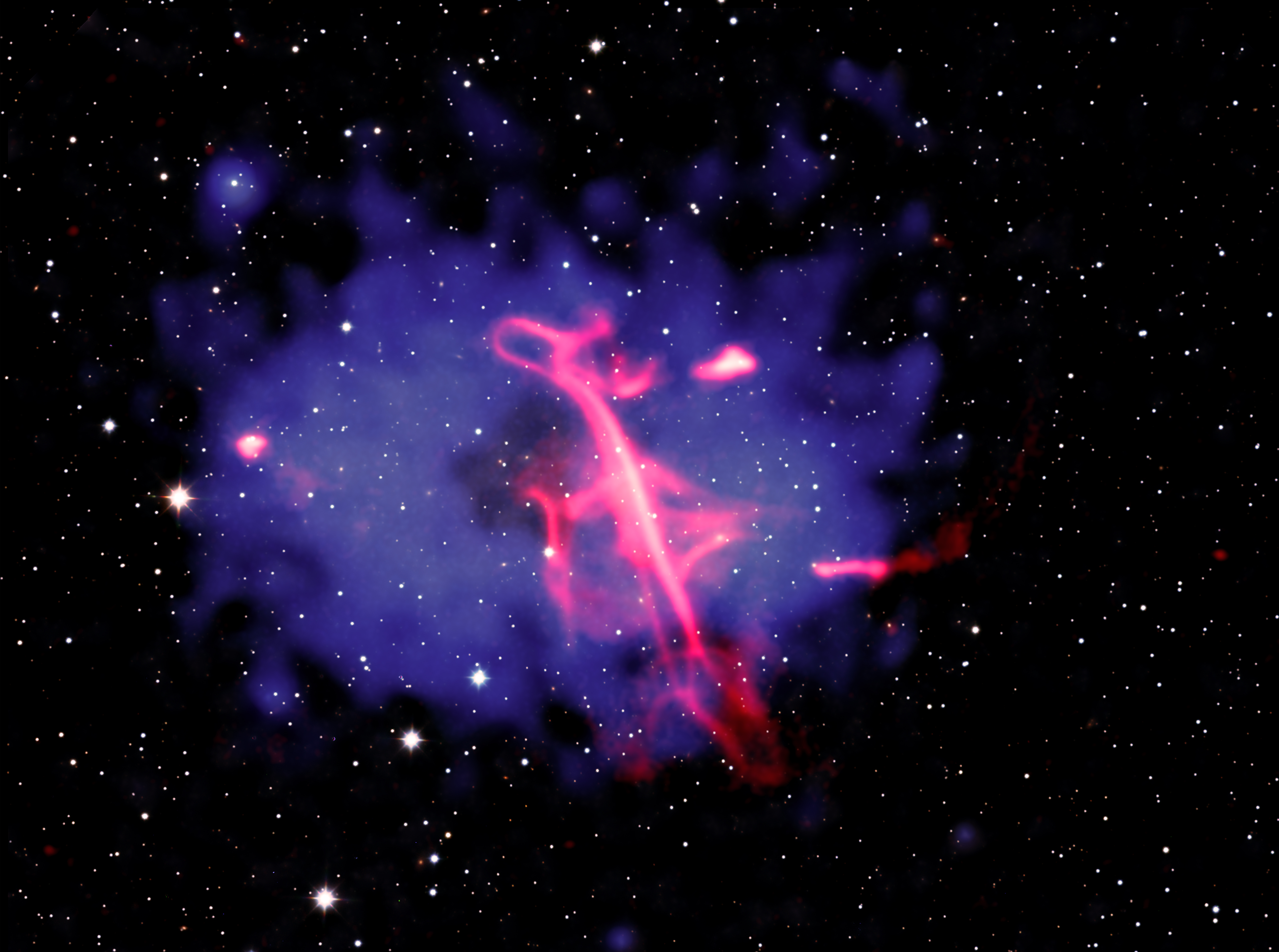
Using Chandra, astronomers have discovered that an outburst from a supermassive black hole, followed by a collision of two galaxy clusters, are the likely causes of an unusual formation in a galaxy cluster. The “Treble Clef” radio source was given its nickname because of a distinct shape in radio waves that resembles the musical symbol. This composite image of the Treble Clef and its galaxy cluster contains X-rays from Chandra and eROSITA, radio data from LOFAR, and infrared data from UKIRT.
X-ray: NASA/CXC/INAF-IRA/A. Botteon et al.; Infrared: UKIDSS-GPS ; Radio: ASTRON/LOFAR; Image processing: NASA/CXC/SAO/N. Wolk

Astronomers have used NASA’s Chandra X-ray Observatory to break down the cause of a remarkable formation of radio waves they have nicknamed the “Treble Clef” because its distinct shape strongly resembles the musical symbol.

The researchers discovered the Treble Clef is likely caused by an outburst from a supermassive black hole, followed by a collision of two galaxy clusters. A paper describing the findings, led by Andrea Botteon of the National Institute for Astrophysics, or INAF, in Italy, published Wednesday in the Astronomy & Astrophysics journal.

An explanation for the Treble Clef has been particularly difficult to find because the formation lies almost directly behind the plane of the Milky Way, meaning that stars, gas, and dust from our home galaxy largely block the view from Earth. However, by using telescopes that can peer through the intervening material, a team of researchers was able to identify what is responsible for this uncommon structure.

NASA’s Chandra and the German Extended RÖntgen Survey with an Imaging Telescope Array (eROSITA) X-ray telescope found diffuse, hot gas at the location of the Treble Clef, showing that a galaxy cluster hosts the object. The researchers also determined the galaxy cluster is, in fact, two clusters in the process of merging. Galaxy clusters are some of the largest structures in the universe, containing hundreds of individual galaxies and huge reservoirs of superheated gas.

This new composite image of the Treble Clef and its cluster shows the multimillion-degree gas detected in X-rays by Chandra and eROSITA in blue, with some of the Chandra data derived from a special technique the authors used to highlight important features in the Chandra data. Radio data shown in red from the LOw Frequency ARray (LOFAR), a large network of radio telescopes in Europe reveals the doppelganger of the musical notation. The final piece of the combined image comes from infrared data obtained by the United Kingdom Infrared Telescope, appearing mostly white.

The authors concluded that the Treble Clef likely formed in a two-stage process. First, an earlier outburst from a supermassive black hole in the galaxy cluster’s center drove clouds of charged particles and magnetic fields away at close to the speed of light. This led to a type of cosmic crescendo and initially produced bright radio waves that later faded as the particles lost energy. Next, the collision between the two clusters compressed or reenergized the cloud, which became brighter again in radio waves. Shock waves — similar to the sonic booms from supersonic jets — from the collision may have played a role in this reenergizing process.

To reveal evidence for the cluster collision in the Chandra data, the authors used a special technique that examined how much the cluster’s hot gas deviates from a symmetrical shape. Most of the hot gas is symmetrical and shaped approximately like an oval. The authors removed this symmetrical oval shape from the original X-ray image. The remaining X-ray emission in the residual image shows t is brightest on the left and right, and faintest in the center. The new composite image combines both the original X-ray and the residual X-ray images.

The brighter X-rays in the residual image, toward the left and right of the cluster’s center, imply that the collision between the two clusters likely occurred along the left-right direction as seen in the image. The researchers think the direct collision between the two clusters occurred a few hundred million years ago, and the clusters are now moving away from each other.

The resemblance to a treble clef is a case of pareidolia, the phenomenon when people see familiar shapes in random data, since there is no scientific connection to the musical notation.

NASA’s Marshall Space Flight Center in Huntsville, Alabama, manages the Chandra program. The Smithsonian Astrophysical Observatory’s Chandra X-ray Center controls science operations from Cambridge, Massachusetts, and flight operations from Burlington, Massachusetts.

To learn more about Chandra, visit:

https://nasa.gov/chandra

Visual Description

This release features a composite image of a remarkable radio wave formation that strongly resembles a treble clef musical symbol, hovering in the midst of two colliding galaxy clusters.

Here, galaxies in the galaxy clusters, plus foreground and background stars and galaxies, blanket the image with specks of light set against the blackness of space. At the center of the frame is a large, oval, blue-purple cloud with ragged edges. This is a multimillion-degree gas cloud in the two clusters detected in X-rays by Chandra and eROSITA, the Extended RÖntgen Survey with an Imaging Telescope Array.

In the middle of the purple field, tilting slightly to our left, is what appears to be a giant treble clef, loosely drawn with a neon pink marker. Like the musical notation for which it’s named, the formation has a strong vertical stroke with a continuous, fluid line swooping back and forth as it moves from top to bottom.

This radio wave formation appears to be the result of a two-stage process. First, charged particles and magnetic fields were driven from a supermassive black hole, producing bright radio waves. Those waves faded and lost energy over time, before being reenergized and compressed when the two galaxy clusters collided.

Share

Details

Last Updated
Oct 15, 2026
Editor
Lee Mohon
Contact
Location
Marshall Space Flight Center
❌